¶ General Description
The function performs a transaction (request/response) according to the ISO TP standard.
During the transaction, a request is sent to the bus, and the received response is written to the receive buffer.
The function uses the RXD buffer
For the function to operate, the following settings must be configured in the device configuration:
Configuration➜CAN Bus
..➜Use built-in CAN interface
..➜Interface operating mode➜active
¶ Graphical Representation
| In the function menu | On the diagram |
|---|---|
 |
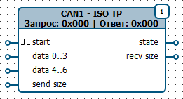 |
¶ Inputs
| Name | Value type | Description |
|---|---|---|
start |
bool |
Send request |
data 0..3 |
int32 |
Lower 4 bytes of data to send |
data 4..6 |
int32 |
Upper 3 bytes of data to send |
send size |
int32 |
Number of bytes to send. Determines how many bytes will be taken from data 0..3 and data 4..6. The remaining bytes are filled with zeros. The send size value is also written to the first byte of the request. The parameter does not change the CAN message length (DLC), it is always 8 bytes |
¶ Outputs
| Name | Value type | Description |
|---|---|---|
state |
int32 |
Receiver state: 0 — receiver disabled 1 — output data is not valid 2 — data received and valid 5 — settings not configured 6 — configuring settings 7 — settings configured -1 — function configured incorrectly or device resources unavailable -2 — error sending data -3 — timeout -4 — invalid response -5 — response not supported |
recv size |
int32 |
Number of bytes received in the RXD buffer. |
¶ Status Transitions
0 -> 5 -> 6 -> 7 -> 1 -> 2 // final status in case of success
               |    |
               |    *--> [-4, -5] // error in the received response
               |    |
               |    *--> -3  // no response received
               |
               *--> -2 // error sending data

[0 .. 7] -> -1  // Transition to an error is possible from any status
¶ Settings
| Name | Description |
|---|---|
| Bus | CAN interface used:CAN1CAN2 |
| Timeout, ms | Time to wait for a response after sending the request. |
| Request identifier | Identifier value used to generate the request |
| Response identifier | Identifier value of the expected response |
| Byte order | Byte order that will be used when sending the source data array to the CAN bus. For example, if data 0..3 = 0x44332211, data 4..6 = 0x776655, then data = [11,22,33,44,55,66,77]: «Least significant first» transmitted = [11,22,33,44,55,66,77] «Most significant first»transmitted = [77,66,55,44,33,22,11] «Most significant first (2 bytes)»transmitted = [22,11,44,33,66,55,77] |
¶ Examples
¶ Example 1
To send a fuel level request according to the OBDII standard, configure the block as follows:
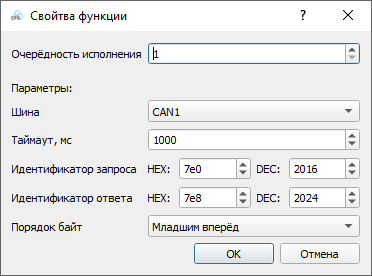
The data for generating the request is supplied to the inputs:
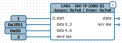
A request with ID 7E0 and data [02,01,2F,00,00,00,00,00] will be sent to the bus.
In response, a message with ID 7E8 and data [03,41,2F,64,00,00,00,00] will be received.
The first byte 03 indicates the number of payload bytes in the response. Therefore, 3 data bytes [41,2F,64] will be added to the RXD buffer.
