¶ General Information
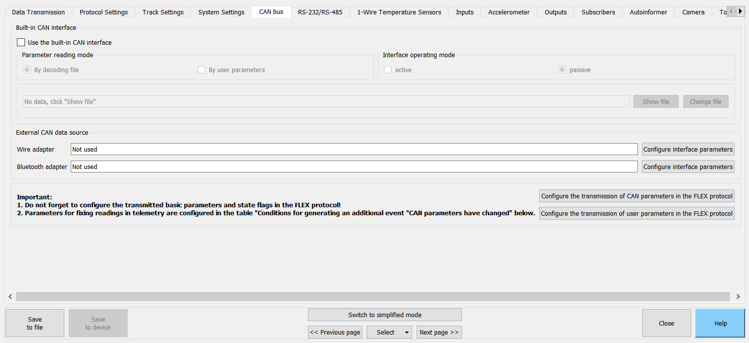
On CAN bus tab, you can configure the processing of data received by the device from:
- CAN interface in the device;
- external CAN adapters (connected to RS-232/RS-485 and Bluetooth interfaces).
You can select two data sources simultaneously.
Description of settings for each of the sources is given below in the Built-in CAN interface and External CAN data source sections.
When selecting at least one of the data sources - Built-in CAN interface ("By decoding file" parameter reading mode) and/or External CAN data source, a list of parameters/commands with which the device can work becomes available.
This part of the configuration is described in the List of parameters section.
When the data received from the CAN bus changes, the event "CAN parameters have changed" can be generated. Description of the setting for determining the conditions for generating additional events is given in the Additional events section.
¶ CAN Interface in the Device
Device is equipped with its own CAN interface, which allows connection to the vehicle's CAN bus without additional adapters/decoders.
Interface can operate in Active or Passive modes:
In the Active mode device "listens" to the CAN bus, can send commands/requests, and also acknowledge messages in the CAN bus.
When using the Active mode, be extremely careful: due to the peculiarities of each individual vehicle, errors may occur in the operation of the vehicle electronics.
In the Passive device only "listens" to the CAN bus.
When using the "Passive" mode, part of the functionality related to reading data from the CAN bus may not be available.
For example, when working with a VDO Continental tachograph, in order to obtain driver card codes, it is necessary to make requests to the CAN bus.
When using the built-in CAN interface, two modes of reading parameters are available:
- By decoding file;
- By user parameters.
Simultaneous use of two modes is not possible.
¶ Decoding file
Decoding file contains all the necessary settings for working with the CAN bus, as well as a list of parameters available for reading.
To work with the CAN bus of a vehicle of a certain make, model and year of manufacture, it is necessary to load the appropriate decoding file from the Configurator library into the device.
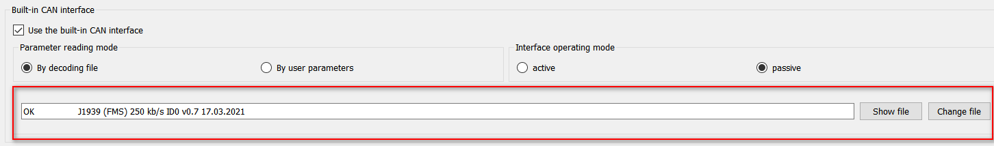
To work with the decoding file, there is a separate area located immediately below the Parameter reading mode area.
To view the list of decoding files and load them to the device, the Configurator must be connected to the device via USB or remotely.
"Line with the name of the file" displays the name of the decoding file loaded into the device.
The file name is requested from the device, so if the device is not connected, the line will not be filled.
After clicking the Show file button, the Configurator will display the name of the decoding file that is currently loaded into the device.
After clicking the Change file button, the Decoding file loading dialog box will open with a list of available files.
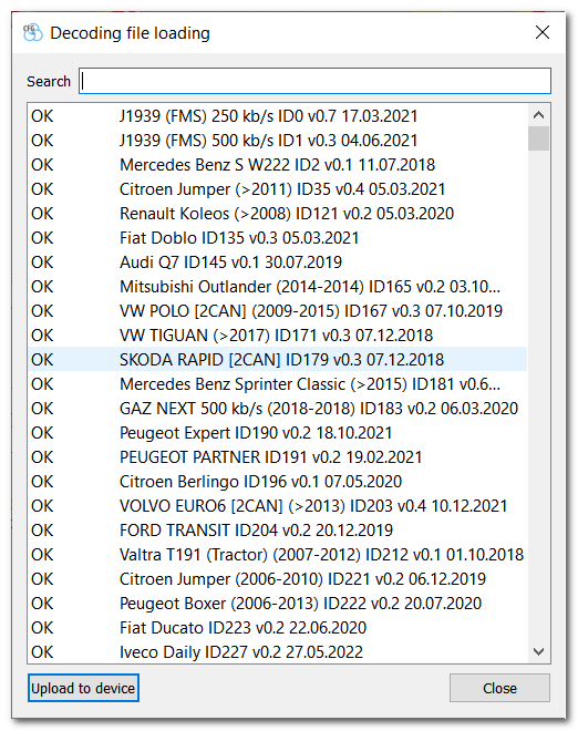
At the top of the window there is a filter by file name for easy search.
- Name format:
<Type format><Make><Model><[Years of manufacture]><File version><File modified date> - Description:
<Type format>- decoding file status:
empty - file not tested;
BETA - test version;
OK - file verified by several users.
<Make>- vehicle brand.
<Model>- vehicle model.
<[Years of manufacture]>- years of manufacture of the vehicle for which the information in the file is relevant.
<File version>- version of the decoding file for this vehicle (the version changes when corrections or improvements are made).
<File modified date>- date when the decoding file was last modified.
To upload a decoding file to the device, select it in the list and click the Upload to device button.
After uploading the decoding file, the List of parameters section will show those parameters that can be read on this vehicle. The description of the section “List of parameters” is given below.
¶ Decoding files library
List of decoding files is updated by updating the Configurator library.
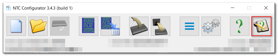
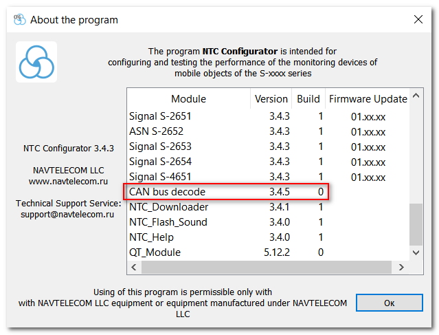
Version of the decoding file is displayed in the Configurator menu About the program.
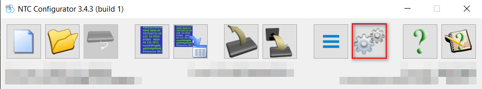
Updating the decoding file is done in the Configurator menu Program settings.
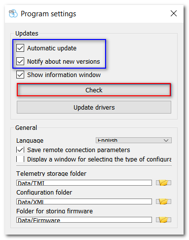
To receive notifications about the availability of new Configurator libraries, you must set the Automatic update and Notify about new versions flags.
If the flag Notify about new versions is not set, then updates will be downloaded automatically without user confirmation.
¶ User parameters
When configuring the CAN interface using User parameters, you need to know exactly:
- CAN bus baud rate;
- type, code of CAN messages identifiers, as well as a set of their parameters;
- whether a request for CAN messages is required.
CAN bus baud rate (Interface speed (bps))- to receive information from the CAN bus, the device must set the CAN interface to a certain baud rate.
If the required interface baud rate is not in the list, then it can be set manually in the same field.
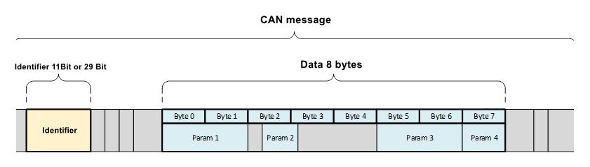
Information exchange in the CAN bus is carried out through the messages exchange. Each message has an ID and a data field. One message can contain several parameters. In turn, each parameter has a specific length and offset (position) within the message data field.
¶ CAN messages area
For further work with the parameters, it is necessary to determine which messages should be received from the CAN bus.
You can set up to receive up to 16 messages.
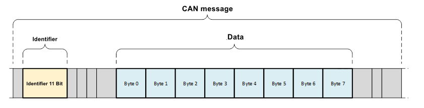
Type is the type of identifier you need to get. There are 3 types of ID:
-
11 bit ID is used in CAN 2.0A buses;
-
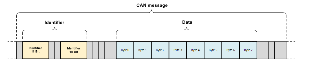
29 bit ID is used in CAN 2.0B buses;
-
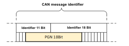
«PGN» is a a particular case of ID format in CAN 2.0B buses.
Identifier field specifies the identifier of the CAN message in hexadecimal representation (HEX).
While in most cases 11- and 29-bit identifiers are presented in the documentation in hexadecimal (HEX), PGNs are usually specified in decimal (DEC).
To convert values from decimal to hexadecimal, you can use the online converters "dec to hex" or the standard Windows Calculator in the Programmer mode.
Period is an interval of a message occurrence in the CAN bus. If the device does not receive this message from the CAN bus for a period of time equal to three periods, then it resets it.
As a result of reseting the message for each parameter received from this message, a special value is set that is unique for each separate type of parameter. Description of the parameter types and the corresponding special value types, is given in the CAN message data section.
On request parameter is only available if the interface is in Active mode. When the flag is set, the device sends a request to the CAN bus to receive this message.
Do not reset - if the flag is set, then the device does not reset this message even if it no longer receives it from the CAN bus.
If you change the Type and Identifier settings or delete a message in the CAN messages area, all lines containing this message will be automatically cleared. Therefore, after changing messages, be sure to check the settings associated with them.
This rule applies to the settings:
- CAN message data (CAN bus tab);
- User parameters (Protocol setting tab).
¶ CAN message data tab
This area describes the parameters that are contained in the received messages in the Data area.
You can configure receiving up to 32 parameters.
Message - after setting up the receipt of the required CAN messages, they become available for selection in this list.
The format for each message is:
<Type><space><Identifier>
For example: 11бит 4fd, 29бит fe65da or PGN fe72.
Because the data field of one message can contain several parameters, it is allowed to select the same message on different lines.
Parameter setting defines the size and type of the parameter to be received from the message. Several combinations of sizes and types are available for selection.
- Sizes:
1,2,4и8bytes.
Size determines in which group of user parameters the received parameter will be transmitted. That is, if the 2-byte parameter is selected, then when setting the protocol, it will be available only in the group of two-byte parameters. - Types:
bitfield,signed data,unsigned dataandreal data(IEEE 754 floating point number). Real data type type is only available for parameters with sizes of 4 and 8 bytes.
The type is important for the correct processing of the conditions for generating events described in the Additional events section, as well as for processing information on the GPS server.
When the message is reseted or if the device does not see the message in the CAN bus, the parameters obtained from this message take the following values:
| Parameter size |
Type | Value at reset |
|---|---|---|
| 1 | bitfield | 00000000 |
| 1 | signed data | -128 |
| 1 | unsigned data | 255 |
| 2 | bitfield | 00000000 00000000 |
| 2 | signed data | -32768 |
| 2 | unsigned data» | 65535 |
| 4 | bitfield | 00000000 00000000 00000000 00000000 |
| 4 | signed data | -2147483648 |
| 4 | unsigned data | 4294967295 |
| 4 | real data | nan (0x7FFFFFFF) |
| 8 | bitfield | 00000000 00000000 00000000 00000000 00000000 00000000 00000000 00000000 |
| 8 | signed data | -9223372036854775808 |
| 8 | unsigned data | 18446744073709551616 |
| 8 | real data | nan (0x7FFFFFFFFFFFFFFF) |
Offset setting allows you to specify in which byte the parameter is located in the data field. If the parameter takes several bytes, then starting from which byte it is located in the data field. An example of the location of parameters in the data field of a CAN message:
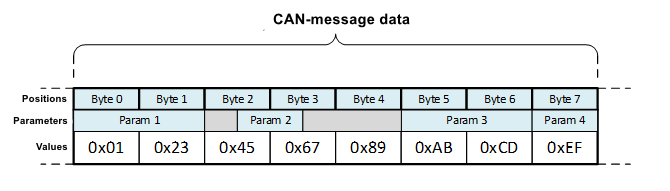
So, according to the example:
Param 4 is located in one byte at offset 7.
Param 2 is located in two bytes at offset 2.
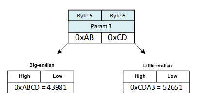
Big-endian setting specifies which byte reading order to use for messages larger than 1 byte. When the flag is set to read the parameter, the Big-endian byte order (high byte on the left) is used, if the flag is cleared, then Little-endian (low byte on the left) is used.
For example:
The Param 3 parameter is 2 bytes in Big-endian byte order and is located in the CAN message at offset 5.
That is, the value of Param 3 consists of two bytes 0xAB (high byte) and 0xCD (low byte).
If reading use Big-endian byte order, the device will store the value of parameter 43981. If reading using Little-endian byte order, then the device will store the value of parameter 52651 (which would be an error for this example).
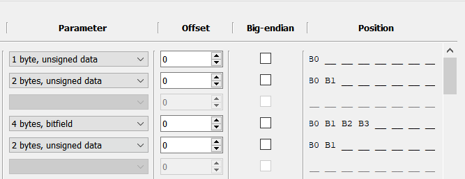
Position field column of CAN message data is not a setting. This is a visual representation of how the device will read the parameter value from the data field of the CAN message, depending on the settings Parameter, Offset and Big-endian (minor byte "B0", "B1" older, etc.).
Upon completion of setting the CAN user parameters, they will become available for selection in the settings:
- Conditions for generating an additional event "CAN parameters have changed"*;
- User parameters (Protocol settings tab).
- Parameter representation format:
UC,<Message>,<Position>,<Type> - Description:
UC- symbolic designation of the CAN user parameter.
<Message>- value selected for this parameter in the Message setting from the CAN message data area;
<Position>- representation of this parameter is the same as in the Position column from the CAN message data area
<Type>- parameter type set in the Parameter setting from the CAN message data area. - Example:
UC,11bit 235,B0 B1 __ __ __ __ __ __,unsigned
UC,11bit 235,__ __ __ __ B3 B2 B1 B0,unsigned
If any settings of the CAN message data parameter are changed, all related lines containing this parameter will be automatically cleared. Therefore, after changing the parameters, be sure to check the related settings.
This rule applies to settings:
- Conditions for generating an additional event "CAN parameters have changed" CAN bus tab;
- User parameters Protocol settings tab.
¶ CAN Adapters
One of the data sources for the device is external CAN bus adapters.
Сorresponding area is designed to display selected external sources for reading data from the CAN bus:

CAN adapters are connected to the device via digital interfaces RS-232/RS-485 and Bluetooth.
The interfaces are configured on the RS-232/RS-485 and Bluetooth tabs, a quick transition to the desired tab can be done by pressing the Configure interface parameters button.
After configuring the interface to work with the CAN adapter, its type will be displayed in the corresponding text field:

After selecting the type of external CAN adapter, the parameters that the device can accept from it will be shown in the List of parameters section.
¶ List of parameters
List of parameters area allows to determine which parameters and commands the device can work with on the settings specified in the Built-in CAN interface and External CAN data source areas.
To display the possibility of working with the parameter, the following indication is used:

- If the device can work with a parameter or a command using the built-in CAN interface, then the parameter is highlighted in green.
- If the device can work with a parameter or a command using an external CAN adapter, then the parameter is in bold.
- If a parameter cannot be obtained with the given device settings, then it is not highlighted in either color or bold.
CAN parameters are divided into two groups:
Basic parameters that are most common in the CAN bus of vehicles. For such parameters, separate fields are reserved in the data communication protocol with a clear description of their purpose and unit of measure. For example, "Fuel level in the tank, l".
Additional parameters that are rare in the CAN bus of vehicles. There are no reserved fields for such parameters in the communication protocol, and they are transmitted as part of user parameters. For example, "Rotation of the hoist boom, 0.1*"..
Each parameter or group of parameters can be selected by setting a flag near its name.
If the flag is set near a parameter or group of parameters from the list Standard parameters, then the name of the parameter or group will become available for selection in the settings:
- Conditions for the formation of addtional event "CAN patameters have changed" (CAN bus tab).
If the flag is set near a parameter or group of parameters from the list Additional parameters, then the name of the parameter or group will become available for selection in the settings:
- Conditions for the formation of addtional event "CAN patameters have changed" (CAN bus tab).
- User parameter (Protocol settings tab).
¶ Additional Events
This group of settings allows setting the conditions for generating user events for changing certain parameters that have been selected in the CAN message data, Readable standard parameters and Readable additional parameters areas.
CAN parameters have changed events are transmitted to the platform with the following codes:
6122 - CAN: Standart parameters have changed;
6123 - CAN: User parameters have changed;
6124 - CAN: Additional parameters have changed.
- In total, no more than 10 conditions can be set to generate additional events.
- Each parameter can be assigned no more than one condition.
Parameter list allows selecting a parameter, changing the value of which will generate an event CAN parameters have changed.
The content of the list changes dynamically depending on the settings in the CAN message data, Readable standard parameters and Readable additional parameters areas. When a new parameter is added in one of the areas, the option to select this new parameter is added to the list, and when removed from, it also disappears from the list.
If a parameter has been selected in the list and a condition has been assigned to it, then in case of changing or deleting a parameter in the area where it was defined (CAN message data, Readable standard parameters and Readable additional parameters), the line with the condition for generating additional events for this parameter will be automatically cleared.
Formation condition - 3 types of conditions are available: Threshold change, Transition across boundaries and Zone entrance/exit. Each type has its own additional settings.

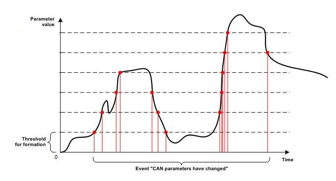
¶ Threshold change
For the function to work, it is necessary to set one setting - Change threshold.
According to this condition, the device fixes as a reference value the first reading of the parameter received after the device was turned on. And each time the parameter value changes by the value of Change threshold relative to the reference value, the device:
- generates an event CAN parameters have changed;
- updates the reference value to the current one.
Below is a figure explaining the operation of the Threshold change condition:
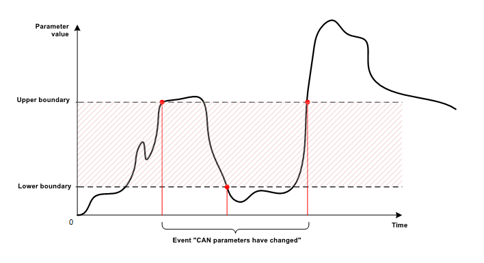
¶ Transition across boundaries
For the function to work, it is necessary to set two settings: Lower boundary and Upper boundary.
According to this condition, the device fixes the facts of the transition of the parameter value up through the border Upper boundary and the transition of the parameter value down through the border Lower boundary.
Below is a figure explaining the operation of the Transition across boundaries condition:
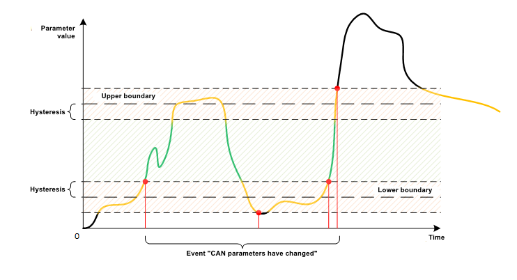
¶ Zone entrance/exit
For the function to work, it is necessary to set several settings: Lower boundary, Upper boundary and Boundary hysteresis.
According to this condition, the device fixes the facts of entry into and exit from the zone formed by the settings Lower boundary and Upper boundary. In this case, to protect against the formation of a large number of entry and exit events, due to fluctuations in the value of the parameter in the border zone, the Boundary hysteresis setting is used.
Below is a figure explaining the operation of the Zone entrance/exit condition: