¶ General Concept
At the CAN bus level, concepts such as vehicle speed, engine RPM, or fuel level do not exist. The CAN bus transmits only messages with a fixed structure, each containing a sequence of raw data bytes.
Each message is a compact data container whose purpose is to deliver information from one Electronic Control Unit (ECU) to other ECUs on the network. The CAN bus itself does not define the meaning of the transmitted data. Without additional protocol documentation, the contents of a message cannot be interpreted.
When working with CAN, the same model always applies:
Message → 8 bytes of DATA → Extract meaningful parameters
¶ CAN Frame Anatomy
Each CAN message consists of three main elements:
- Identifier (ID) – 11 or 29 bits
- Data Length Code (DLC) – 4 bits
- DATA – 0 to 8 bytes

The Identifier (ID) defines the message type. It is not the address of the receiving ECU. Instead, it identifies what kind of data the message contains.
Two identifier formats are defined:
- Standard Identifier – 11 bits
- Extended Identifier – 29 bits
The only difference is the number of available identifier values. The extended format provides a much larger identifier space and is commonly used in systems requiring a greater number of unique messages.
¶ PGN (Parameter Group Number)
In the extended CAN format (29-bit identifier), the identifier itself may contain an internal structure defined by the communication protocol.
For example, the SAE J1939 protocol divides the 29-bit identifier into several fields, including Priority, PGN, Source Address, and others.
The PGN (Parameter Group Number) defines:
- the type of transmitted data
- the structure of the DATA field
Conceptually:
- ID is the message container.
- PGN defines the meaning of the message.
Each PGN corresponds to one message definition, while only the parameter values change from message to message.
In practice, CAN filtering is often performed using the PGN rather than the complete 29-bit identifier.
¶ Extracting the PGN from a 29-bit Identifier
| Bits | 28..26 | 25 | 24 | 23..16 | 15..8 | 7..0 |
|---|---|---|---|---|---|---|
| Field | Priority | R | DP | PF | PS | SA |
The PGN consists of 18 bits:
- R + DP + PF + PS
Not included in the PGN:
- Priority
- SA (Source Address)
The DLC (Data Length Code) specifies the size of the DATA field. In Classical CAN, the value ranges from 0 to 8 bytes. In most applications, the maximum payload size of 8 bytes is used.
The DATA field contains the actual payload. It is simply an array of bytes, each having a value between 0 and 255. This field contains all parameters in their raw, unprocessed form.
Although every CAN frame has the same structure, the meaning of the DATA field depends entirely on the protocol implemented by the vehicle manufacturer.
¶ DATA as a Sequence of Bytes
One of the most important characteristics of CAN is that it does not transmit ready-to-use parameter values. It transmits only sequences of bytes.
For example:
ID: 0x123
DLC: 8
DATA: 0A 1F 00 64 FF 10 03 7C
At this level, these bytes have no physical meaning. Their interpretation is impossible without a protocol description defining:
- which bytes belong to each parameter;
- how those bytes should be combined;
- how the resulting value should be converted into engineering units.
As a result, the same byte sequence may represent completely different parameters in different vehicles.
¶ Byte Order (Endianness)
Whenever a value occupies more than one byte, the byte order becomes important.
Two byte orders are commonly used:
- Little Endian – Least Significant Byte first.
- Big Endian – Most Significant Byte first.
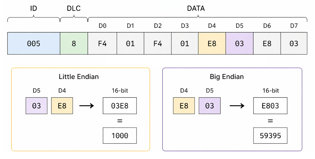
The same bytes may therefore represent different numeric values depending on the selected byte order.
Incorrect byte order is one of the most common causes of decoding errors. Without knowing the endianness, it is impossible to reconstruct the original value correctly.
¶ Data Types Inside the DATA Field
The DATA field is a continuous sequence of bytes that may contain many different types of information. Parameter boundaries are defined by the protocol and are not necessarily aligned with byte boundaries.
A single byte may represent:
- a group of independent flags (bit field);
- a complete numeric value;
- part of a larger numeric value.
Integer values may occupy one or more bytes, requiring correct interpretation of both bit length and byte order.
An important point is that the same byte may simultaneously belong to multiple parameters when different parameters use different bits within that byte.
¶ Extracting a Value from 8 Bytes
Extracting a parameter from the DATA field consists of several steps.
First, determine which bytes belong to the parameter. Then determine the byte order. Next, combine the bytes into a numeric value. Finally, apply the scaling factor.
Consider a simple example.
Suppose the parameter occupies two bytes:
DATA: ... 0x0A 0x1F ...
Assuming Big Endian format:
0x0A 0x1F → 0x0A1F → 2591
If the scaling factor is 0.1, the resulting parameter value becomes:
2591 × 0.1 = 259.1
At this stage, the important concept is that bytes are not the final value. They represent encoded information that must be decoded.
Scaling factors and parameter definitions are covered in detail in the following module.
¶ Interpretation Limitations
Without a protocol description (DBC, CAF, or a similar definition file), CAN data has little practical meaning. It is impossible to determine:
- where a parameter begins;
- how many bits it occupies;
- which byte order is used;
- how the value should be converted.
Even if changing bytes appear to correlate with changes in vehicle behavior, this alone does not guarantee that the parameter has been interpreted correctly.
Practical CAN decoding always begins with hypotheses that must be validated by analyzing logs and comparing them with real vehicle events.
¶ Practical Exercise
- Download the sample log from the previous module:
- Open CAN Spy.

- Set Source to Log player, then open the downloaded log.
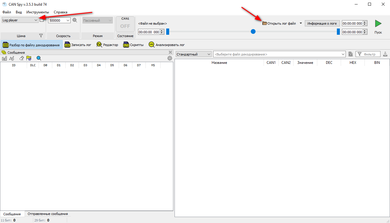
- Click Start. The messages will appear in the Messages window.
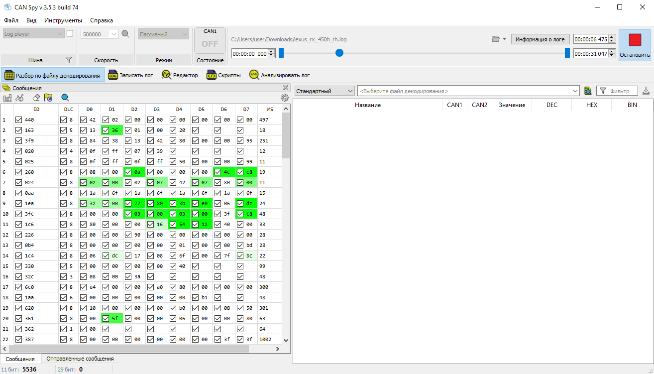
If the Messages window is hidden, enable it from the View menu.
Sort the messages by identifier and observe their transmission frequency.
Keep in mind that the identifier itself does not determine how frequently a message is transmitted. The transmission period is defined entirely by the ECU's internal logic. The message ID affects only bus arbitration priority.
¶ Module Summary
A CAN message is simply a container holding up to eight bytes of raw data. The interpretation of those bytes is defined entirely by the communication protocol.
To decode a parameter, you must determine:
- which bytes contain the parameter;
- the correct byte order;
- the conversion rule used to obtain the final value.
The process of converting raw bytes into engineering values is covered in the following modules.
 Back to Contents
 Collecting and Preparing Data for Analysis