¶ Introduction
Unlike discrete parameters, dynamic numeric parameters change continuously and cannot be held at a single fixed value. Instead, they vary within a certain range. To decode such a parameter, you must determine which value on the CAN bus corresponds to the value displayed on the vehicle dashboard.
¶ Logs
Recommended recording procedure:
- Start recording a video.
- Capture the moment when log recording begins to synchronize the video with the CAN log.
- Record the dashboard display showing the parameter of interest.
- Change the parameter by increasing the engine RPM, accelerating the vehicle, or performing similar actions.
A video recording is essential because it:
- allows the exact moment of a parameter change to be synchronized with the CAN log, down to individual events;
- makes it possible to analyze the log later, including by another engineer;
- preserves the overall context, showing other dashboard indicators that may assist during analysis.
Instead of changing the parameter randomly or repeatedly cycling through the same values, it is recommended to follow a predefined sequence. This produces a more recognizable graph.
In this example, the following sequence is used to identify the engine RPM parameter:
Idle → Smooth increase in several steps up to maximum RPM → Return to idle → Three rapid throttle blips → Engine stop.
In addition, record a Background Log without changing the parameter. This captures the normal operating state of the vehicle.
¶ Log Analysis
Knowing how the parameter changed during recording, compare the logs and look for a graph that follows the same pattern. The objective is to find a signal whose shape matches the behavior of the parameter.
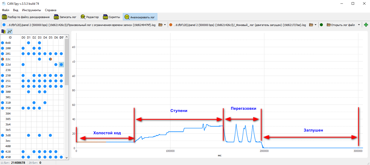
Not every changing signal represents the desired parameter. The important criterion is the correlation of the signal shape, not simply the presence of changes.
Once a candidate signal has been found, determine how many bits are used to represent the parameter.
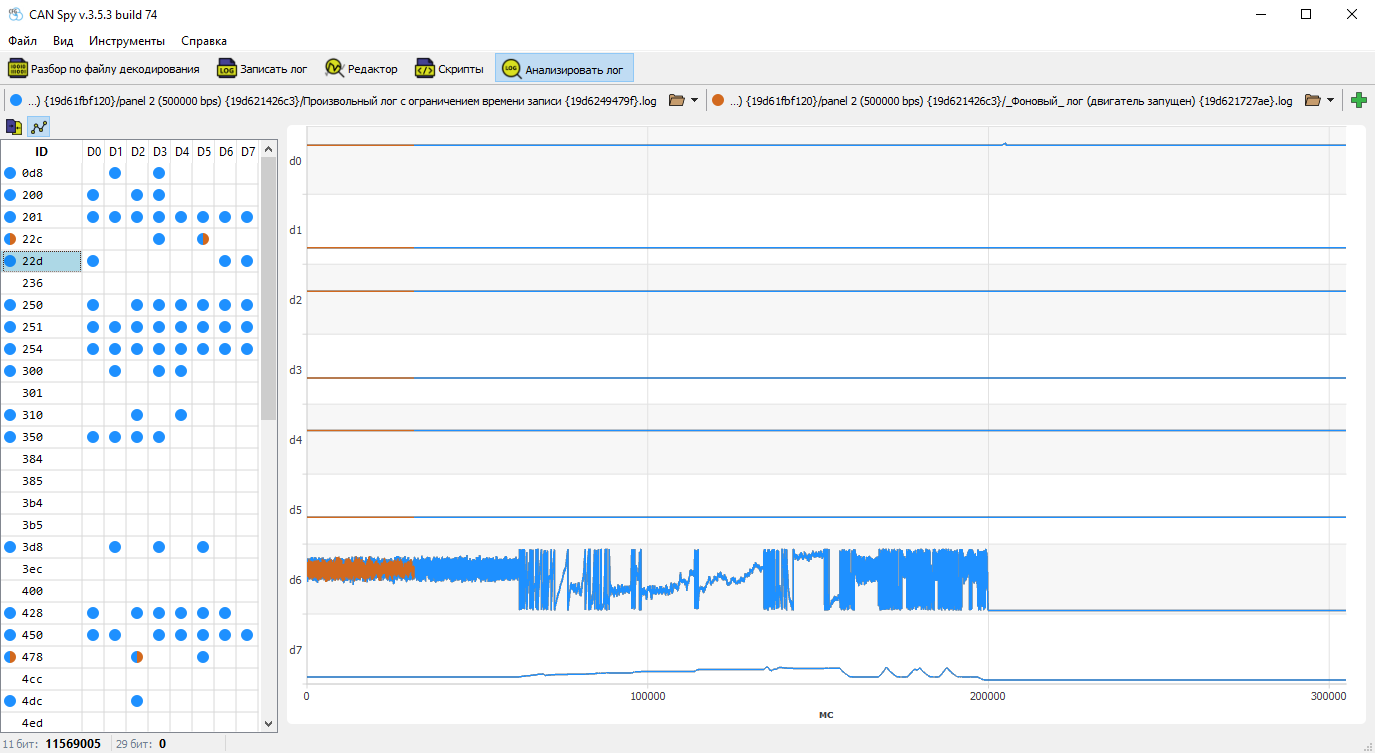
In this example, when byte D6 overflows, the value of D7 increases. This indicates that the parameter occupies these two bytes, with D7 being the most significant byte. Therefore, the parameter uses Little Endian byte order.
¶ Creating the Parameter
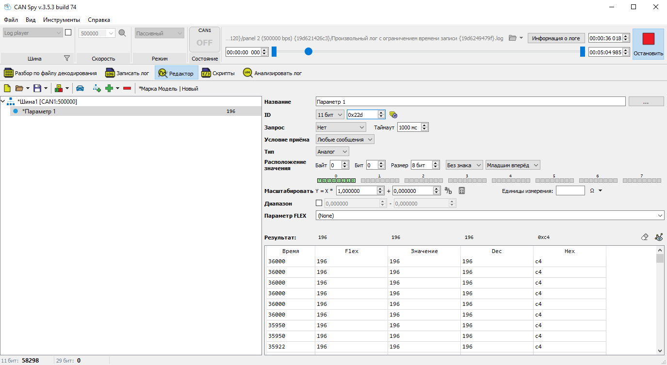
Create a new parameter in the Editor and specify the message ID.
Configure a 2-byte bit mask with an offset of 6 bytes, using Little Endian byte order.
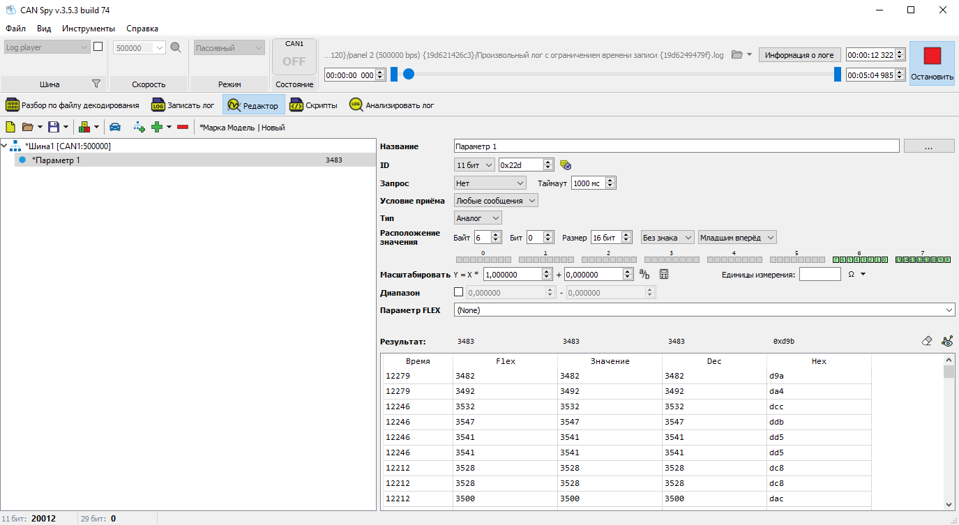
Before configuring scaling, assign the FLEX parameter, since for some parameters it affects the final transmitted value.
¶ Scaling
After applying the bit mask, the raw CAN value is obtained. This value must then be converted to match the value displayed on the vehicle dashboard.
A linear transformation is used:
Where:
- x – raw CAN value
- y – dashboard value
- k – scaling factor
- b – offset (typically 0)
¶ Determining the Scaling Parameters
Select two corresponding values (CAN ↔ dashboard) and calculate the scaling factor:
In most cases:
- b = 0
- k is a simple fraction such as 1/2, 1/4, or 1/10.
In this example, a scaling factor of 1/4 = 0.25 is used to convert the raw CAN value into the engine RPM displayed on the dashboard.
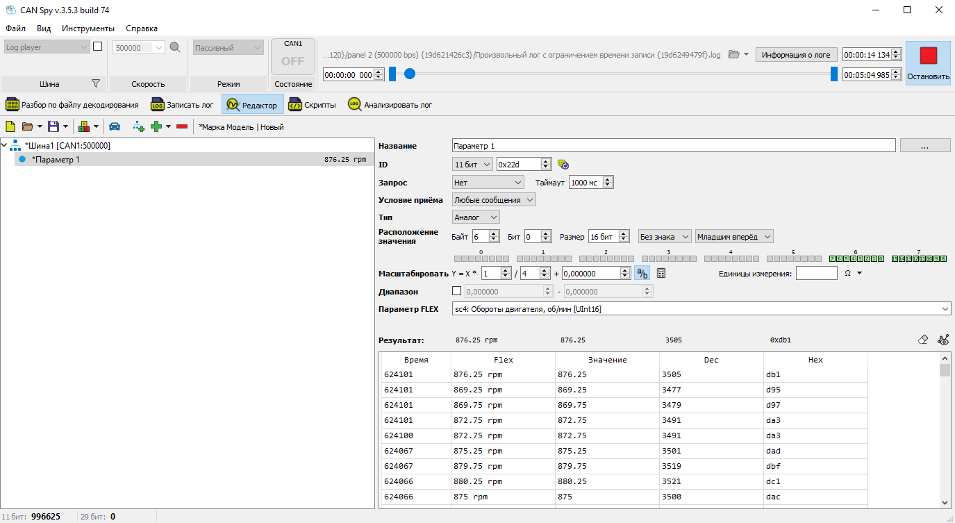
The built-in Scaling Calculator can be used to calculate the scaling factor.
¶ Defining the Valid Range
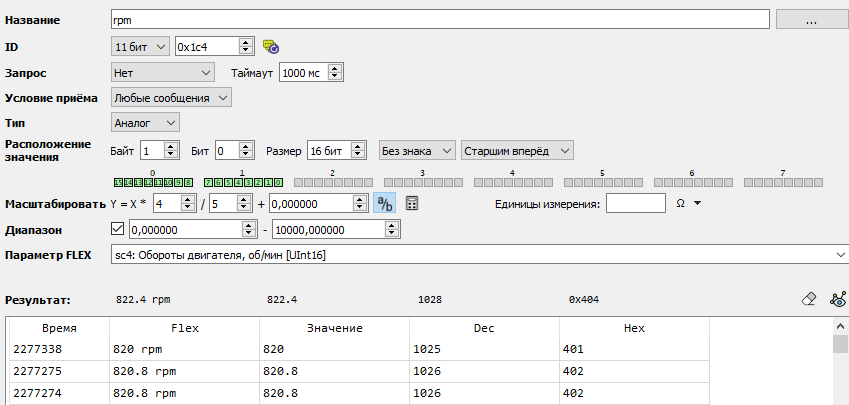
Specify the range of valid parameter values. This helps filter out invalid or noisy data.
For parameters such as Fuel Level and Odometer, it is usually recommended to exclude zero, since these values may briefly appear when the ignition is switched on.
Important: The valid range is applied to the Value column, which may differ from the FLEX value.
¶ Verification
After the parameter has been configured, the final value is displayed in the FLEX column of the results table.
Compare this value with the dashboard reading shown in the video recorded during log capture.
¶ Practical Exercise
Identify the Engine RPM parameter yourself.
Logs:
The video recorded for the Simple log with limited recording time log is available here.
 Back to Contents
 Finding Static Numeric Parameters