¶ Introduction
Discrete parameters are generally the easiest to identify because their states are simple to reproduce and observe. They usually have a limited number of possible values, such as ON/OFF, allowing you to isolate the effect of a single action.
For example, you can fasten and unfasten the driver's seat belt without significantly affecting other vehicle systems. In contrast, changing the engine RPM simultaneously affects many other parameters, including throttle position, fuel consumption, engine temperature, battery voltage, and more.
¶ Logs
In most cases, only two logs are required:
- Background Log (Ignition ON)
- Custom Discrete Sensor
When recording the Background Log, do not perform any actions on the vehicle. The purpose of this log is to capture the normal system state.
When recording the Custom Discrete Sensor log, interact only with the sensor being analyzed.
The result is two logs with nearly identical CAN traffic. The differences between them make it much easier to identify the messages associated with the selected sensor.
This approach works only when a single action changes a single sensor. If one action affects multiple sensors simultaneously (for example, when engaging an axle lock activates two indicators), this method is no longer sufficient. In this case, the Custom Discrete Sensor log contains only two combined states: everything active and everything inactive, making it impossible to separate the individual sensor responses.
In such situations, record a Background Log (Ignition ON) together with a video recording. The video allows you to determine the exact timing and sequence in which each sensor changes state.
¶ Log Analysis
The most convenient way to identify the sensor response is to use the Analyze Log tool.
Load both logs into the analyzer and assign a different marker color to each one. In the summary table on the left, look for bytes marked with the color assigned to the Custom Discrete Sensor log. Selecting one of these bytes should display a graph corresponding to the periodic switching of the sensor.
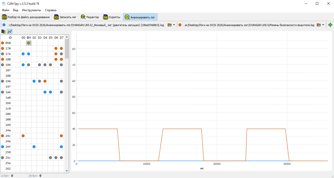
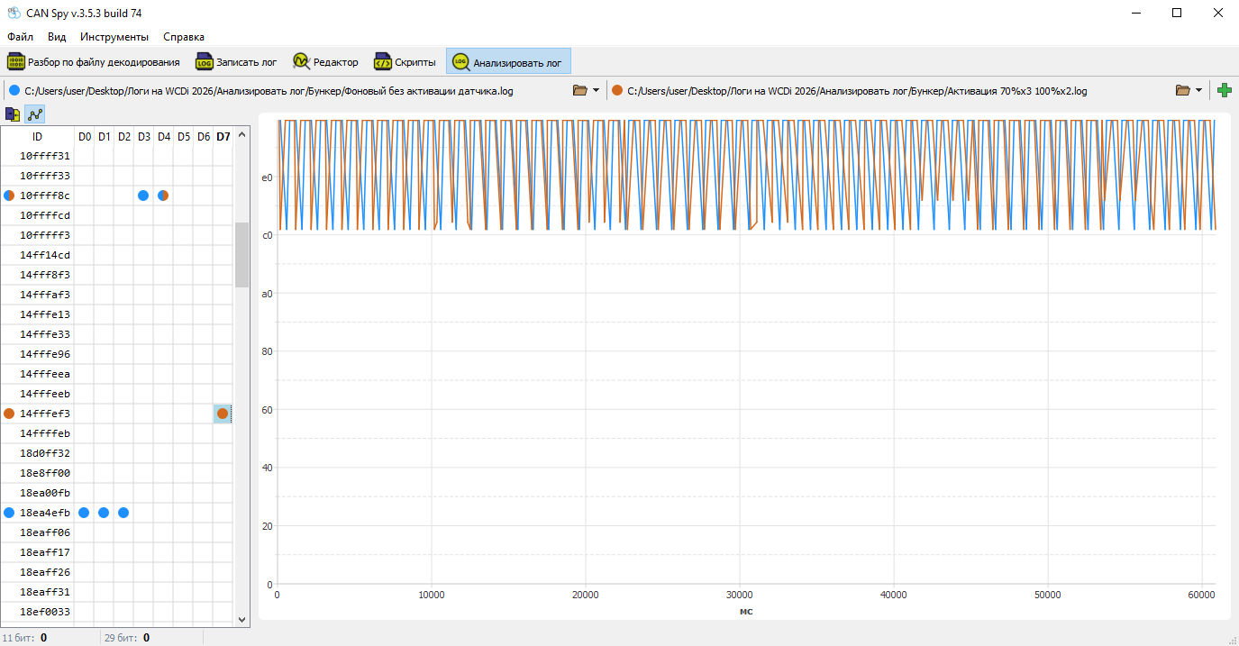
The graph may not always show an obvious pattern. However, the presence of a marker indicates that this byte differs from the background log, making it a candidate for further analysis using filters and conditions.
Example:
¶ Creating the Parameter
After identifying candidate signals, you can configure the parameter and verify that it correctly detects the sensor state.
For easier verification, start playback of the recorded log.
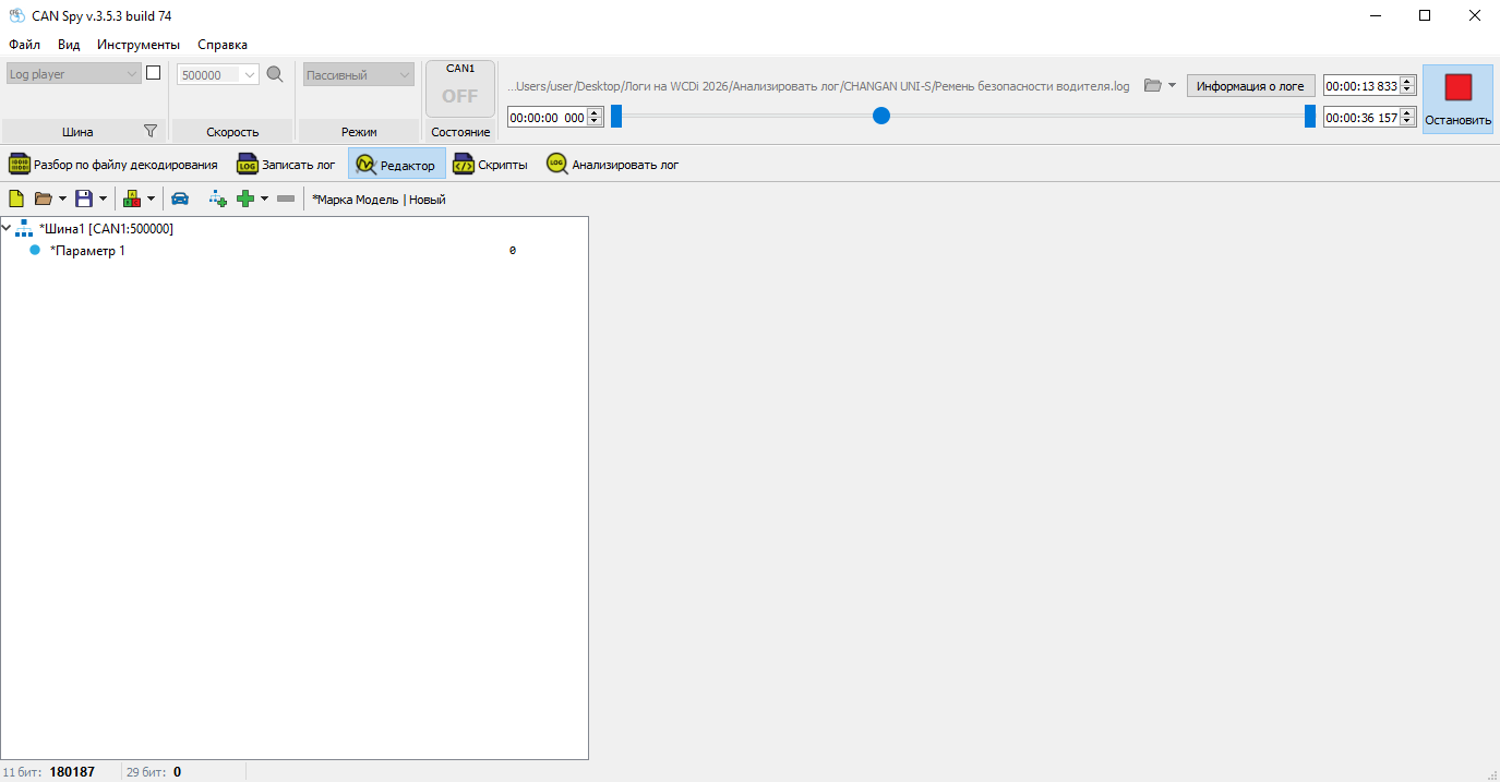
Open the Editor tab and create a new parameter.
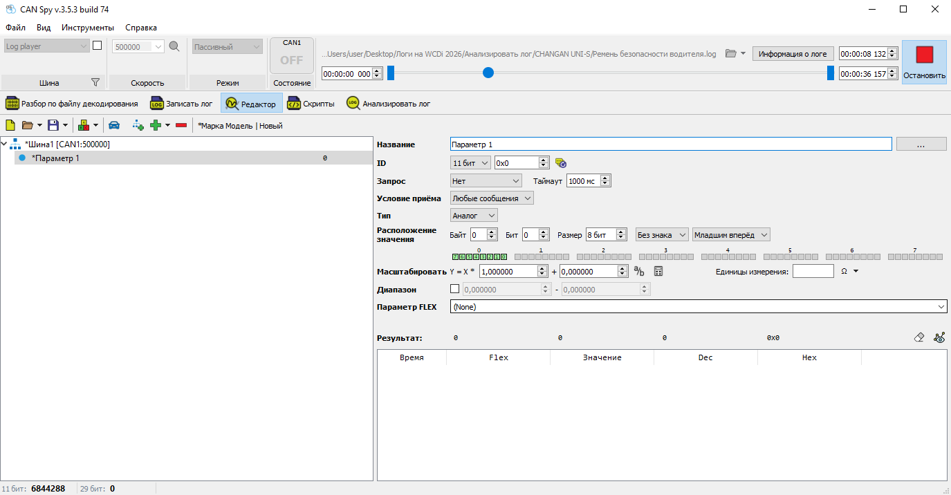
First, configure the ID and the byte number containing the value. Once these settings are applied, decoded values should appear in the results table.
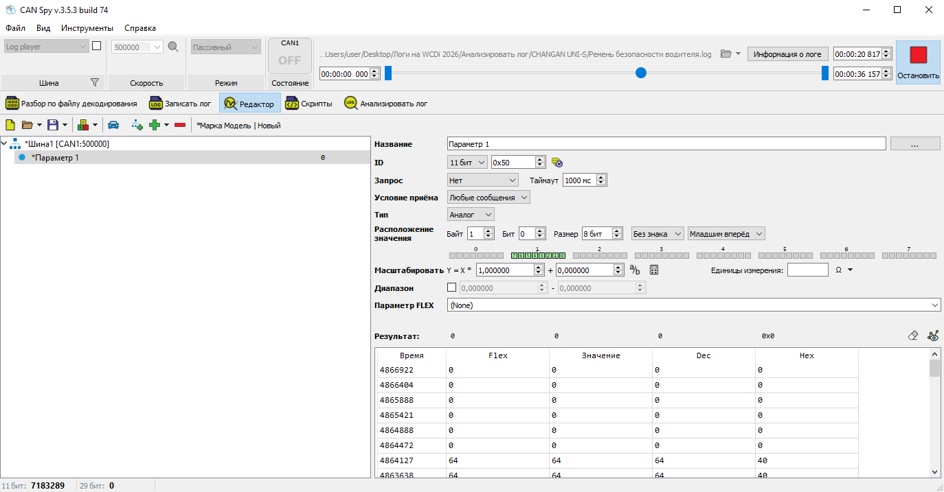
In this example, the observed values are 0 and 64. This does not mean that the entire byte represents the sensor state. In most cases, only one or two bits contain the actual information, and these bits must be isolated using a bit mask.
This can be done manually if the bit layout is known, or by using the Byte Analysis tool, which highlights the active bits.
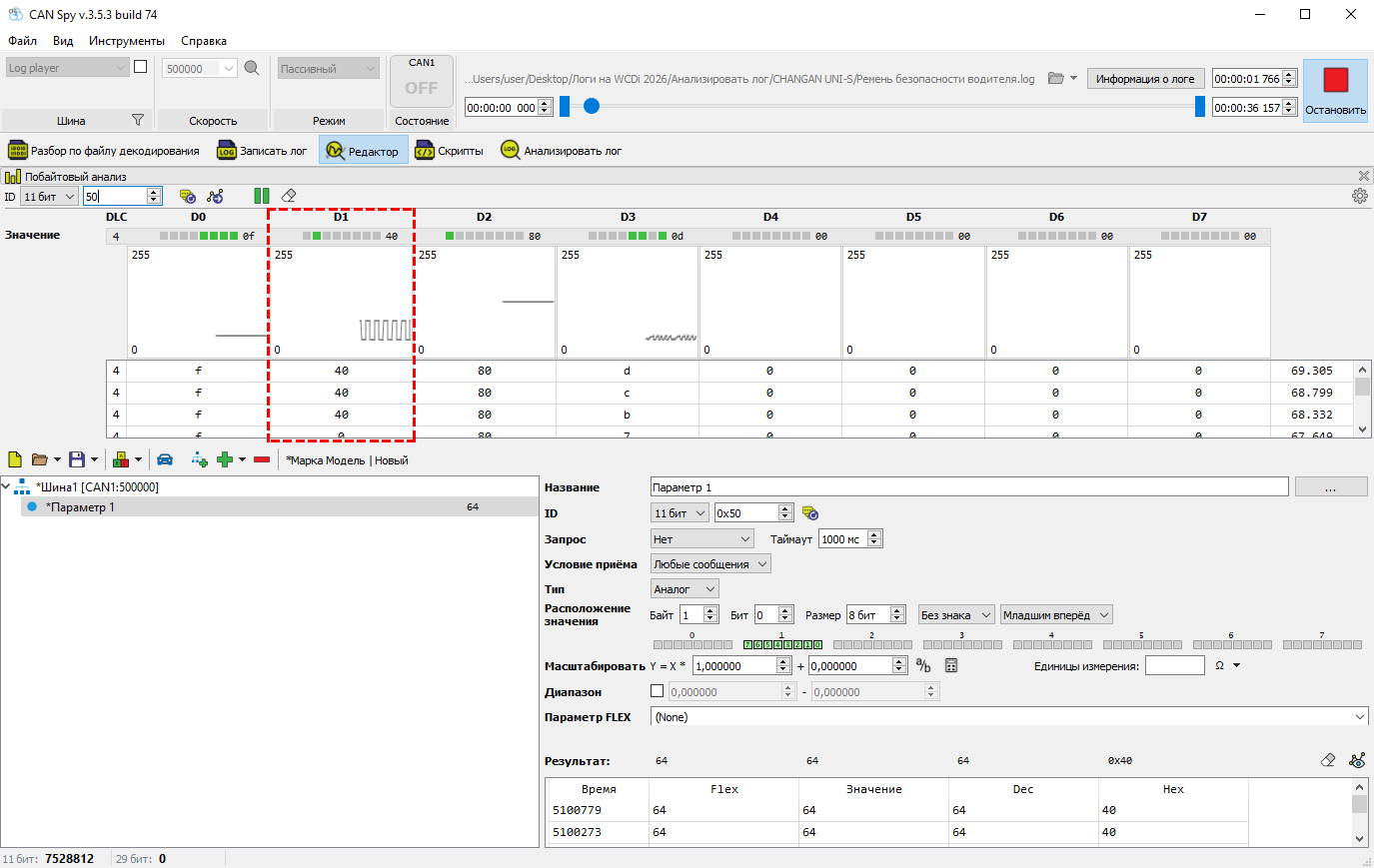
The change may involve a single bit (0 → 1) or multiple bits (01 → 10).
After identifying the correct bits, specify the Mask Length (in bits) and the First Bit Position.
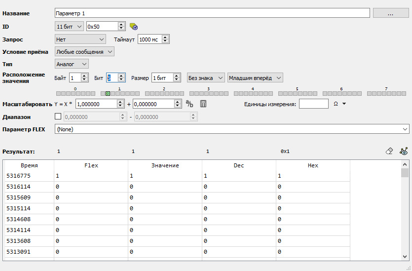
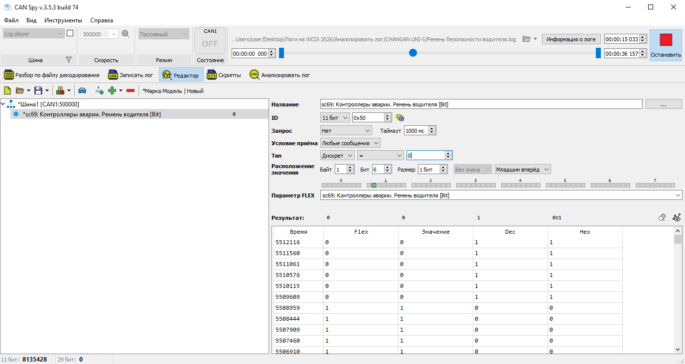
Next, set the parameter type to Discrete and define the condition under which the parameter value becomes 1.
For example, the driver's seat belt signal is often active when the belt is not fastened. For easier interpretation, it is usually better to invert the signal. As a result, the parameter Crash Controllers. Driver Seat Belt will have the value 1 when the seat belt is fastened.
Finally, configure the FLEX parameter and assign the parameter name.
¶ Verification
After the configuration is complete, the FLEX column in the results table displays the final parameter value.
¶ Practical Exercise
Download the archive:
vw_tiguan_(2016_-_2016)_discrete.7z
The archive contains logs recorded while changing the following parameters:
- Brake Pedal
- Driver Seat Belt
- Driver Door
- Selected Gear
The Selected Gear log was recorded with the engine running. All other logs were recorded with the ignition switched on.
Decode these parameters yourself.
¶ Solution
Compare your results with our CAF file:
vw_tiguan_(2011-2016)_v1.0.caf
 Back to Contents
 Finding Dynamic Numeric Parameters