¶ General Description
Program uploaded to the device is compiled using graphic elements. Graphical description consists of two diagrams: Flowchart and Function Block Diagram.
First, on the left side of the editor, general Flowchart is drawn up, then on the right side of the editor, each element of the flowchart is described in detail in the form of a Function Block Diagram.
Any Complex Events program works on the principle of an infinite loop, i.e. after the execution of the last instruction described in the diagram, program starts the execution from the first instruction and so on.
¶ Flowchart
Flowchart is a general algorithm of the program, which consists of blocks (steps) interconnected by lines indicating the direction of the execution sequence. Following blocks are supported:
- Start – beginning of each cycle of the program, is always present on the flowchart in a single number.
- End – ending of each cycle of the program, is always present on the flowchart in a single number.
- Action – data processing block.
- Condition – data processing block with condition, allows continuing the program in one of two ways. This block allows changing the sequence of program execution for programming conditions and loops.
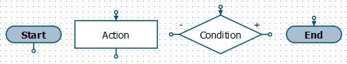 |
| Appearance of blocks |
Starting from the Start block, blocks are executed one after another in a user-defined sequence (execution order is determined by lines). When the program reaches the End block, it means the end of the processing of the current loop. Loops are infinitely executed one after another, from the Start block to the End block.
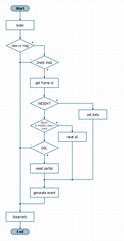 |
| Flowchart example |
¶ Function Block Diagram
In the right part of the editor, data processing diagram is drawn up for a specific block (Actions or Conditions) from the left part. This circuit consists of interconnected functional blocks (functions), constants and variables.
Function block diagram is essentially similar to the CFC (Continuous Function Chart) programming language, which is designed for programming PLCs (programmable logic controllers).
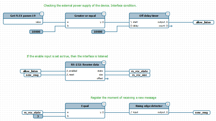 |
| Function block diagram example |
 Previous Guide
 Next Guide