¶ Elements Description
¶ Start and End blocks
Start indicates the beginning of each program cycle. Also program execution begins from this point at the first start or restart.
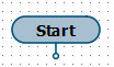 |
| Start block |
End – indicates the ending of each program cycle. When this point is reached, the program proceeds to the execution of the next cycle (goes to the Start block).
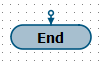 |
| End Block |
Blocks are present on the diagram in a single number and cannot be deleted.
¶ Action block
This block is used to describe one or more functions. Block has one input and one output, which allow placing it in the flowchart and show the direction of the program run.
After execution of the last function of the Action block, program proceeds to the execution of the block which is connected to the output.
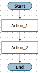 |
| Example of including Action block into flowchart |
¶ Condition block
This block is used to describe decision points in the program depending on the conditions specified by the user. As in the Action block, within Condition block one or more functions are described. Condition block has one input and two outputs: Output + and Output -, which allow placing it on the flowchart and show the direction of the program run.
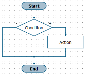 |
| Example of including Condition block into flowchart |
Distinctive feature of the block is presence of result system variable, which is located inside the block (on the right side of the editor). Result variable cannot be deleted or copied. For the block execution, result variable must contain True or False condition.
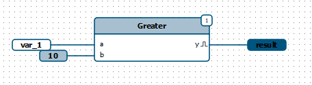 |
| Example of connecting the result variable inside the Condition block |
After execution of the last function of the Condition block, program checks the value of result variable, and if the value is True, then program proceeds to the execution of the block connected to the Output +, if the value is False, program proceeds to the execution of the block connected to the Output -.
 |
| Decision point and program execution depending on the value of result variable |
¶ Creating a Flowchart
As mentioned above, Start and End blocks are present in the program in single number, they cannot be deleted and copied. Only their position can be changed on the flowchart.
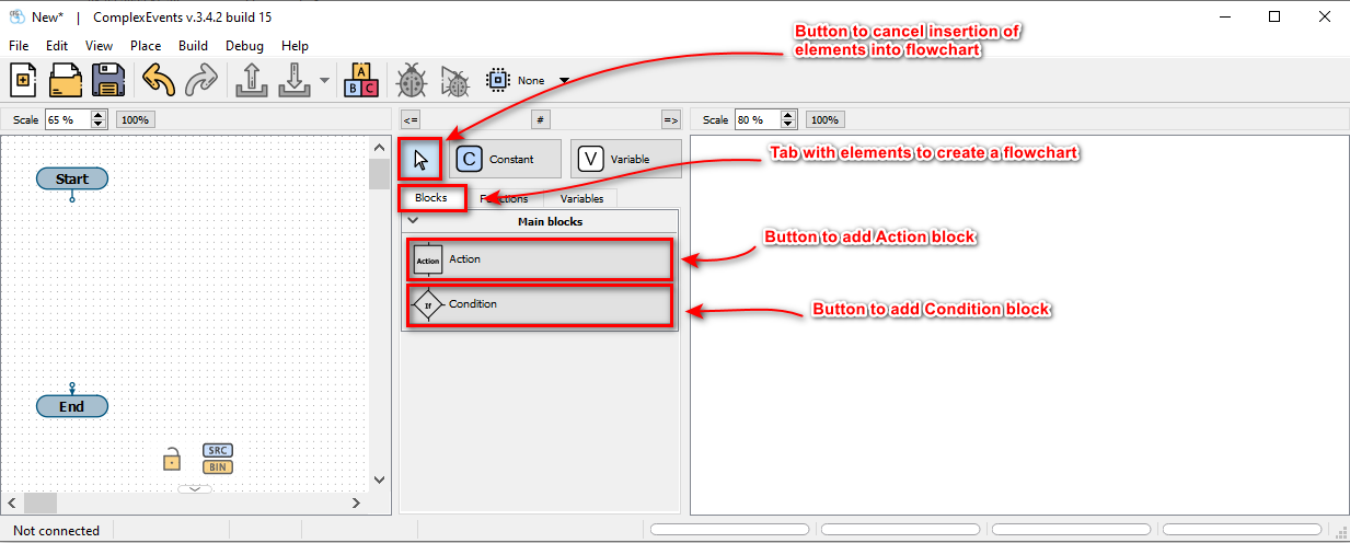
Action and Condition blocks can be added to the flowchart in required numbers. For that go to the Blocks tab on the panel in the middle part of the application and use one of two ways to move blocks to the flowchart:
- Selection by the first click, placement by the second click
Left-click the required block in the Main Blocks group, then move the cursor to the flowchart editor (in the left part) and left-click again, the selected block will be added to the flowchart. - Drag’n’drop
Point to the required block in the Main Blocks group, then grab it (hold down the left mouse button) and move the cursor to the flowchart editor (in the left part). Release the block (release left mouse button), the selected block will be added to the flowchart.
To cancel adding a block, press the Esc key, or click the Arrow button. Blocks can be assigned a name and description, for this it is needed to double-click the block or right-click and select the Properties menu item (duplicates the main menu item Edit - Properties). Enter the appropriate parameters in the appeared dialog box. Block description is displayed when it is hover the cursor over it.
Blocks execution order is determined by the user with the help of connecting lines. Connected pins form a chain. To connect two pins, it is needed to click on the first pin, a line will appear, then click on the second pin. Direction of the lines can be changed by clicking in the required places during the creation process (after clicking on the first pin). Pin can be connected to an existing chain by clicking on the pin first, then on the chain. To cancel creating a chain, press the Esc. Chain can contain multiple outputs and one input. Case where the chain contains more than one input will result in a compilation error. Block inputs are indicated by an arrow. All pins of blocks in the flowchart must be connected.
Each block added by the user contains its own function block diagram (on the left side of the application).
 Previous Guide
 Next Guide