¶ Elements Description
¶ Constants and Variables
In order for the user to set the required initial state of the program, as well as to receive and process the results of the program, elements Constant and Variable are used.
Constant is a constant value which is determined at the stage of drawing up the program and which is not changed during execution of the program.
 |
| Constant on the diagram |
Variable is a named memory area which is used to write, read, and store various values. Value of the variable is determined when the program is compiled and can subsequently change constantly during execution of the program.
 |
| Variable on the diagram |
¶ Properties
Constants and variables have properties that can be changed by the user. To open the properties window, you must double-click Constant or Variable or right-click and select the menu item Properties (duplicates the main menu item Edit - Properties).
| Name | Applicability | Description |
|---|---|---|
| Name | Variable | Text name that allows you to refer to the value of each specific variable (read or change it). Maximum name length is 16 characters. |
| Type |
Variable Constant |
Range of valid values and size allocated in memory for a constant or variable depend on the type. Int32 - signed integer. Float - floating-point number. Bool - boolean (logical) type that has two values True или False.
Type conversion in Complex Events: “INT32 to FLOAT” and back “FLOAT to INT32”: “FLOAT/INT32 to BOOL”: “BOOL to FLOAT/INT32”: |
|
Value |
Variable Constant |
Type of displaying the number value with the INT32 type during debugging (during calculations displaying does not anyhow affect the result). DEC - Number HEX- Number BIN - Number ASCII - Number |
| Value |
Variable Constant |
Value that constant or variable will take when the program starts. |
|
Write access |
Variable | If the flag is set, then when debugger is running, user can change value of the variable manually without stopping the program. |
¶ Function blocks
Function block (function) – is a block that has a certain number of inputs and outputs.
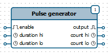 |
| Function on the diagram |
Inputs of the function receive data (for example, from other blocks), then this data is processed and generated into those, which is sent to the outputs of this function (these outputs can be connected to the inputs of other function blocks). Functions are executed one after the other. Execution order is determined by the sequence number.
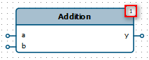 |
| Sequence number for function execution |
For a complete list of functions and their detailed descriptions, see the Function Block Library section.
¶ Creating a Function Block Diagram
When you select a block on the flowchart (on the left side), its function diagram appears on the right side of the application. Function diagram can contain Function Blocks (functions), Variables and Constants interconnected. Lines on the function block diagram indicate the direction of data flow.
To add a function to the diagram, go to the Functions tab on the panel in the middle part of the application and use one of two ways to move blocks to the diagram:
-
Selection by the first click, placement by the second click.
Left-click on the required function, then move the cursor to the function block diagram editor (in the right part) and left-click again, the selected function will be added to the diagram. -
Drag’n’drop.
Point to the required function, then grab it (hold down the left mouse button) and move the cursor to the function block diagram editor (in the right part). Release the block (release the left mouse button), the selected function will be added to the flowchart.
To cancel adding a function, press Esc or click Arrow button.
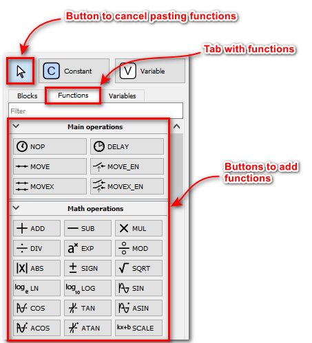 |
| Elements for creating a function block diagram |
Constants and Variables are added in the same way as functions, for this there are Constant and Variable buttons.
When using Variable button, new variable will always be added to the diagram. To add a previously created variable to the diagram, go to the Variables tab and select the one you need from the list. This tab displays all user-added variables. The same variable can be added to different function block diagrams.
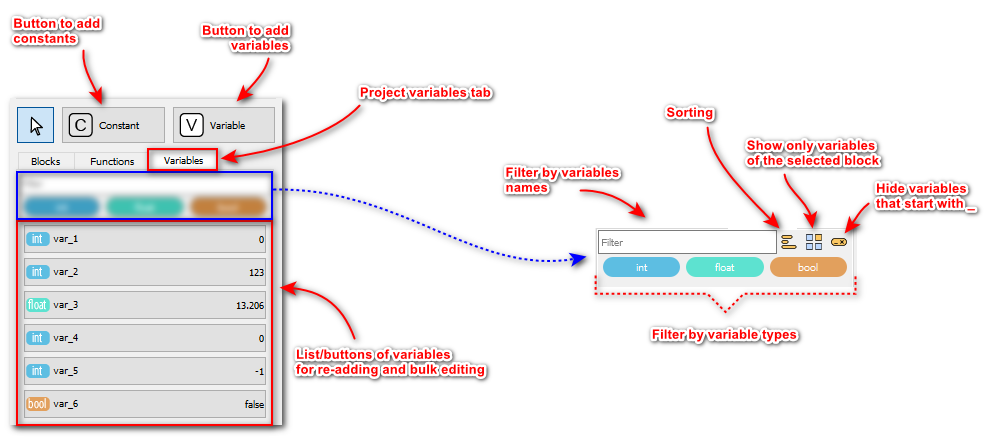 |
| Elements for creating a function block diagram. Variables tab. |
To quickly find variable on the diagram, you need to click the Search button for the required variable.
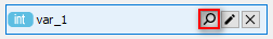 |
| Search button in the list of variables |
You can read more about the search interface in the Variable Search section.
Function inputs are always located on the left part and outputs are always located on the right part. Connection of the elements pins of the functional diagram is carried out as in the flowchart. Connected pins form a chain.
There can be only one function output in a chain, only one variable or constant. If there is an output in the chain, then the constant should not be connected to this chain.
It is not necessary to connect all function pins to the chain.
Functions are executed sequentially one after the other. In the upper right corner, the sequence number of the function is displayed, which determines the order of execution.
 |
| Sequence number for function execution |
The lower the sequence number, the sooner the function is executed. To change the sequence number is possible by double-clicking on the function or by right-clicking and selecting the Properties menu item. Then in the appeared dialog box, change the value of the Execution index. In this dialog box, it is possible to change other parameters of the functions, if they are provided for it.
Editor provides mechanism for automatic numbering of functions, detailed description is given in the Automatic Numbering of Function Blocks section.
 Previous Guide
 Next Guide