¶ General Information
All necessary parameters in the device must be configured according to the Modbus technical description (Register Map) for the connected device.
It is not possible to configure the Navtelecom terminal without a Register Map for the connected device.
Navtelecom terminal works with Modbus devices only in the Master mode.
When connecting a Modbus device to Navtelecom terminals, you can get up to 32 different parameters.
General description of the Modbus protocol is given in the guide Modbus Protocol.
Following Modbus protocol functions are supported:
-
0x01(DO) – read values from multiple coils (Read Coil Status/Discrete Output Coils). -
0x02(DI) – read values from several discrete inputs (Read Discrete Inputs/Discrete Input Contacts). -
0x03(AO) – read values from multiple holding registers *(Read Holding Registers/Analog Output Holding Registers). -
0x04(AI) – read values from multiple input registers (Read Input Registers/Analog Input Registers).
It is possible to receive from Modbus device and transmit to server following parameters:
- 1 or 2 bytes in size with following representation: bit field, signed and unsigned numbers;
- 4 or 8 bytes in size with following representation: bit field, signed, unsigned and real numbers (floating point number by IEEE 754 standard).
¶ Configuration
To configure Navtelecom terminal to work with Modbus device, you need:
- Specify the interface settings (baud rate, parity, number of stop bits) and select the Modbus operation mode in the drop-down list for Device #1:
- Set addresses and parameters of the registers in the Readable parameters field.
- If necessary, set the conditions for generating the additional event "Modbus parameters changed".
- Be sure to configure the data transfer protocol in the Protocol Settings tab in the User Parameters section.
If, after completing the Modbus setup in the RS-232/RS-485 and Protocol settings tabs, you need to change the settings in the Readable parameters field (change address of the sensor or register, parameter size), you need to configure these parameters again in the "Condition for generating" area of the additional event "Modbus parameters changed" and in the Protocol Settings-> User Parameters tab.
¶ Readable Parameters
To configure each Modbus parameter, you must tick On checkbox for it.
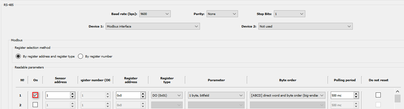
Sensor address – network address of the connected device in the Slave mode, in the range from 1 to 247. Sensor address must match the address set in the Modbus device settings, as well as the Baud rate, Parity and Stop Bits parameters.
Register address - register addresses for each parameter must be set in accordance with the Register Map provided in the documentation for the Modbus device.
Address values in the device setup must be entered in hexadecimal (HEX) form.
Sometimes numbers of registers are indicated in device descriptions, usually they are given in decimal (DEC) representation. In this case, you need to translate the address value from DEC to HEX using the Windows calculator in the engineering or programmer mode.

Register address should not be confused with Register number, which is usually given in decimal form.
For example, the first register, AO Holding Register, has number40001, but its address is0x0000.
Relationship between Register address and Register number concepts is presented in the table:
| Register number DEC |
Register address HEX |
Offset | Name | Modbus function code (Register type) |
|---|---|---|---|---|
| 1 - 9999 | 0x0000 - 0x270E | 1 | Discrete Output Coils | 0x01 (DO) |
| 10001 - 19999 | 0x0000 - 0x270E | 10001 | Discrete Input Contacts | 0x02 (DI) |
| 30001 - 39999 | 0x0000 - 0x270E | 30001 | Analog Input Registers | 0x04 (AI) |
| 40001 - 49999 | 0x0000 - 0x270E | 40001 | Analog Output Holding Registers | 0x03 (AO) |
To convert addresses to numbers each register type (
DO,DI,AI,AO) in the table has its own offset (respectively: 1, 10001, 30001 and 40001).For example, when requesting a value from register
0x5Ewith function0x03(AO), device will return the value from register40095. Register address is0x5E(hex) =94(dec), register number94 + 40001 = 40095.When requesting a value from register with the same address
0x5Eusing the0x01(DO) function, device will return the value from register number95. Register address is0x5E(hex) =94(dec), register number is94 + 1 = 95.
Register type – defines the function of the Modbus protocol to be used.
Following functions are available: 0x01 (DO), 0x02 (DI), 0x03 (AO), 0x04 (AI).
Parameter - setting determines the size of the parameter (1, 2, 4 or 8 bytes) and its representation (bitfield, signed, unsigned, real number).
To determine this setting for each parameter, you can use the Register Map from the device documentation, which indicates how many bytes are allocated for the parameter and what type of data is used.
Type of parameter representation affects the operation of the event generation algorithm and display of information on the telematics server. In order for events to be generated in accordance with the condition set in the setting (see below), its representation must be specified correctly.
Coil
0x01(DO) and Discrete Inputs0x02(DI) registers contain 1 bit in each address, with possible values1= ON (enabled) and0= OFF (disabled).
Therefore, if when polling0x01(DO) or0x02(DI) in the Parameter settins the size is1 byte, then terminal will send a request to the Modbus device to receive values from 8 registers by 8 addresses, starting from the address of the requested register.
If the size of 2 bytes is set in the Parameter setting, then values from 16 registers at 16 addresses will be received, and so on.Input Registers
0x04(AI) and Holding Registers0x03(AO) are ModBus standard 2 bytes (16 bits) with possible values from0to65535.
If when polling0x04(AI) or0x03(AO), 2 bytes are specified in the Parameter setting, value of one register will be received, if 4 bytes are specified, then value of 2 registers will be requested at two addresses, starting from the address of the requested register.
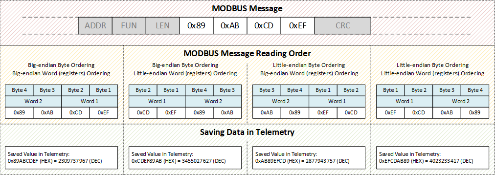
Byte order - this setting allows to control the order in which data is read from the registers.
In the Modbus protocol, register values are transferred starting from the specified address in ascending order of addresses, two bytes per register, the Most Significant Byte of each register is transmitted first (big-endian). However, there is no strict rule describing how to store and transfer values larger than the size of a single register (2 bytes). Cases where the order of bytes in the register differs from the specified (little-endian) are rare, but possible.
Below is a picture explaining how the reading order setting of two registers (words) works:
Polling period – period for polling register values. Can be set individually for each parameter.
Do not reset – if the checkbox is ticked, then if there is no response to the request 3 times in a row, the value from the last response from the device will be fixed, otherwise the value will be reset to a special one (for the selected parameter type).
When "resetting" a parameter or if the terminal does not receive a parameter from an external device, following values are set:
| Parameter size |
Type | Value at reset |
|---|---|---|
| 1 | bit field | 00000000 |
| signed | -128 |
|
| unsigned | 255 |
|
| 2 | bit field | 00000000 00000000 |
| signed | -32768 |
|
| unsigned | 65535 |
|
| 4 | bit field | 00000000 00000000 00000000 00000000 |
| signed | -2147483648 |
|
| unsigned | 4294967295 |
|
| real | 0x7FFFFFFF (nan) |
|
| 8 | bit field | 00000000 00000000 00000000 00000000 00000000 00000000 00000000 00000000 |
| signed | -9223372036854775808 |
|
| unsigned | 18446744073709551616 |
|
| real | 0x7FFFFFFFFFFFFFFF (nan) |
¶ Additional Events
Conditions for generating an additional event “ModBus parameters have changed".
This group of settings allows you to set the conditions for generating the "Modbus parameters have changed" events by changing the parameters that were selected in the settings area Readable parameters.
"Modbus parameters have changed" event is sent to the server with the code
event_code=41056.
For a complete list of event codes, see this page.
In total, up to 10 conditions can be set to generate additional events.
Parameter - this list allows to select a parameter, changing the value of which will generate the event "Modbus parameters have changed".
Content of the list dynamically changes depending on the Readable parameters Modbus settings area. When a new parameter is added to one of the areas, the option to select this new parameter is added to the list, and when it is removed, it disappears from the list as well.
If a parameter was selected in the list and a condition was assigned to it, then in case of changing or deleting the parameter in the Readable parameters area, string with the condition for generating additional events for this parameter will be automatically cleared.
Condition for generating - 3 types of conditions are available:
- Change to threshold,
- Bounds crossing,
- Zone entrance/exit.
Each type has its own additional settings.
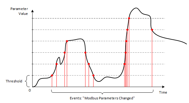
¶ Change to Threshold
For this function you need to set one setting - Change threshold.
According to this condition, device fixes as a reference value the first reading of the parameter received after the device was turned on. And each time when the parameter value changes by the Change threshold value relative to the reference value, device:
- generates event "Modbus parameters have changed";;
- updates the reference value to the current one.
Below is a picture explaining how the Change to Threshold condition works:
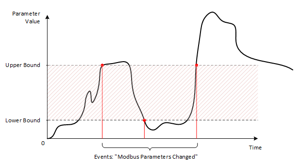
¶ Bounds Crossing
For this function you need to set several settings - Lower bound, Upper bound.
According to this condition, device fixes the facts of the transition of the parameter value upwards through the Upper border and the transition of the parameter value down through the Lower border.
Below is a picture explaining how the Bounds Crossing condition works:
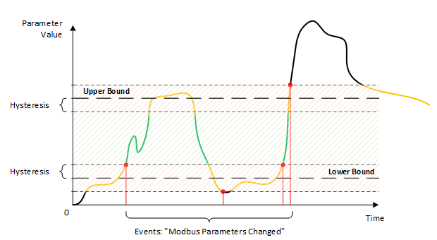
¶ Zone entrance/exit
For this function you need to set several settings: Lower bound, Upper bound, Bound hysteresis.
According to this condition, device captures the facts of entry and exit from the zone formed by the Lower bound and Upper bound settings. At the same time, to protect against the formation of a large number of entry and exit events, due to fluctuations in the value of the parameter in the boundary zone, Bound hysteresis setting is used.
Below is a picture explaining how the Zone entrance/exit condition works: